Learning USB HID in Linux Part 7 - Understanding Keyboard Report Descriptors and Reports
The below is the Report Descriptor of USB Keyboard connected to my system:
usbhid-dump -d 413c:2107 | tail -n +2 | xxd -r -p | hidrd-convert -o spec
Usage Page (Desktop), ; Generic desktop controls (01h)
Usage (Keyboard), ; Keyboard (06h, application collection)
Collection (Application),
Usage Page (Keyboard), ; Keyboard/keypad (07h)
Usage Minimum (KB Leftcontrol), ; Keyboard left control (E0h, dynamic value)
Usage Maximum (KB Right GUI), ; Keyboard right GUI (E7h, dynamic value)
Logical Minimum (0),
Logical Maximum (1),
Report Size (1),
Report Count (8),
Input (Variable),
Report Count (1),
Report Size (8),
Input (Constant),
Report Count (5),
Report Size (1),
Usage Page (LED), ; LEDs (08h)
Usage Minimum (01h),
Usage Maximum (05h),
Output (Variable),
Report Count (1),
Report Size (3),
Output (Constant),
Report Count (6),
Report Size (8),
Logical Minimum (0),
Logical Maximum (255),
Usage Page (Keyboard), ; Keyboard/keypad (07h)
Usage Minimum (None), ; No event (00h, selector)
Usage Maximum (FFh),
Input,
Usage Page (Consumer), ; Consumer (0Ch)
Usage (00h),
Logical Minimum (-128),
Logical Maximum (127),
Report Size (8),
Report Count (8),
Feature (Variable),
End Collection
Analysis of Report Descriptor:
Usage Page (Desktop), ; Generic desktop controls (01h)
Usage (Keyboard), ; Keyboard (06h, application collection)
The above means that the report is intended for a generic USB Device, in this case a keyboard.
Usage Page (Keyboard), ; Keyboard/keypad (07h)
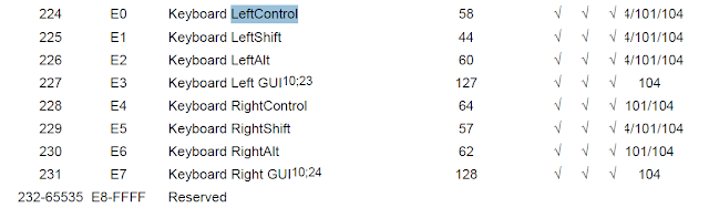
Usage Minimum (KB Leftcontrol), ; Keyboard left control (E0h, dynamic value)
Usage Maximum (KB Right GUI), ; Keyboard right GUI (E7h, dynamic value)
Logical Minimum (0),
Logical Maximum (1),
Report Size (1),
Report Count (8),
Input (Variable),
This defines the modifier keys in the input report. This defines 8 fields which are 1 bit long each, resulting in the modifier byte mentioned previously. The values stored in these fields must be in the range [224, 231], as these are the key codes defined for the modifier keys

KB LeftControl Usage ID is e0 and KB Right GUI is E7 - So 8 usages in sequence
Left GUI is the Left Windows Key and Right GUI is the Right Windows Key.
So, the first byte will contain the information about the Controls (Ctrl, alt, shift, Win (both Right and left))
Report Count (1),
Report Size (8),
Input (Constant),
This defines the constant/reserved byte in the input report, which is again formed by 8 fields which are 1 bit long each.
Report Count (5),
Report Size (1),
Usage Page (LED), ; LEDs (08h)
Usage Minimum (01h),
Usage Maximum (05h),
Output (Variable),
Report Count (1),
Report Size (3),
Output (Constant),
The next 5 bits are for LED and and 3 bits are constant
This defines LEDs that can be set in the output report, formed by 5 fields which are 1 bit long each. LEDs are specified in the following order:
Num Lock
Caps Lock
Scroll Lock
Compose
Kana
For example, a value of 3 (011) will set LEDs Num Lock and Caps Lock.
As I mentioned previously, output reports are 1 byte long. The block above set 5 bits, so it is necessary to add 3 constant fields which are 1 bit long each in order to complete the byte.

Report Count (6),
Report Size (8),
Logical Minimum (0),
Logical Maximum (255),
Usage Page (Keyboard), ; Keyboard/keypad (07h)
Usage Minimum (None), ; No event (00h, selector)
Usage Maximum (FFh),
Input,
Finally, this specifies the key codes pressed in the keyboard in the input report. As shown, the block specifies 6 fields which are 8 bits (1 byte) long each. The value of each field corresponds to the HID code of the key pressed, in the range [0, 255].

Input reports (sent from keyboard to computer) have the following structure for a total of 8 bytes:
1 byte: modifier keys (Control, Shift, Alt, etc.), where each bit corresponds to a key
1 byte: unused/reserved for OEM
6 bytes: pressed key codes
While output reports (sent from computer to keyboard) have the following structure:
1 byte: LED states (Num lock, Caps lock, etc.), where each bit corresponds to a LED
References:
https://www.rmedgar.com/blog/using-rpi-zero-as-keyboard-report-descriptor

Well very thanks for such a nice information! Now please check out this - backlit keyboard
ReplyDelete