Posts

Showing posts with the label Arduino

Blinking LED on Lillypad Arduino
Image
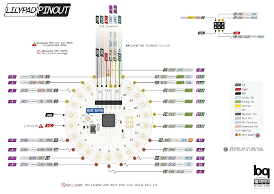
1. Connect VCC,GND of FTDI board to Lilypad 2. Connect RX of FTDI Board to TX of Lilypad 3. Connect TX of FTDI Board to RX of Lilypad as per the below diagram 4.Open Arduino IDE. Files->Examples->Basic->Blink. 5. Select proper serial port and set Board to Lilypad Arduino (Atmega328p) 6. Burn the program. If you get the following errror: avrdude: stk500_recv(): programmer is not responding Press Reset Button while programmer is running.
Arduino HC-05 (Bluetooth) Interfacing

Image
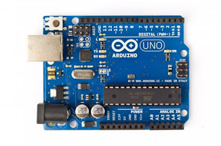
In this post we will access Arduino over Bluetooth either through ur PC or Android device. This will be useful in case when you have sensors interfaced to ur arduino board and want to send this information to ur Mobile. Things needed to do this experiment: 1. Arduino Uno 2. HC-05 Connections: 1.Connect TX of HC-05 to TX of Arduino 2.Connect RX of HC-05 to RX of Arduino 3.Connect GND of HC-05 to GND of Arduino 4.Connect VCC of HC-05 to 5V of Arduino Power up the device either by connecting USB or a battery. Now you can scan this on your PC or Android device to see whether your device is listed out. For example in Ubuntu I can run  hcitool scan and it lists out all the Bluetooth devices. Now you can see a device with name HC-05 in the list. This means your HC-05 is working properly. You can also check the same on your Android device. Now you have to pair your Ubuntu Bluetooth with HC-05. In order to achieve this: 1.Go to Bluetooth Icon, and cli...

Arduino HC-05(ZS-40) AT Commands

Image
The Bluetooth Module HC-05 can be act as Master and Slave. By default it is a master . It can also be configured to have different baud rates:9600, 19200,38400 etc. By default the baud rate is 38400. If you want to modify these settings. It can be acheived by sending AT Commands to the HC-05 Module. In order to send AT commands , you have to connect HC-05 Module to an USB-to-TTY module. If you dont have that like me and have an arduino board then you can use it for sending AT Commands. In order to achieve this, Open Arduino IDE Upload an empty sketch to the Arduino void setup() { } void loop() { } Connections: 1. Connect RX pin of Arduino to RX pin of HC-05(Not the other way:RX to TX) 2. Connect TX Pin of Arduino to TX pin of HC-05 . Don't connect power then before this, you have to switch HC-05 Module to AT Mode. It can be achieved in two modes: 1.One is to hold the switch and then apply the power to it, i.e. connecting VCC of Arduino to HC-05 VCC an...

C Program to read the serial data from arduino

#include <stdio.h> #include <fcntl.h> #include <sys/types.h> #include <sys/stat.h> #include <sys/ioctl.h> #include <termios.h> int main(int argc, char *argv[]) { int fd; char buff[100]; struct termios options; fd = open("/dev/ttyACM0", O_RDWR|O_NOCTTY|O_NDELAY); if (fd == -1) { perror("Error Opening File\n"); return -1; } printf("File Opened Successfully\n"); /* Check if the file descriptor is pointing to a TTY device or not */ if (!isatty(fd)){perror("Not a tty\n");} /* Get the current configuration of the serial interface */ tcgetattr(fd, &options); cfsetispeed(&options, B9600); cfsetospeed(&options, B9600); options.c_cflag &= ~PARENB; /*No Parity*/ options.c_cflag &= ~CSTOPB; /* 1 Stop Bit */ options.c_cflag &= ~CSIZE; options.c_cflag |= CS8 ; /*8 Bits*/ options.c_cflag &= ~CRTSCTS; /*no hardware flow control*/ ...

Arduino pure programming part-6 uart loopback test

Connect the TX and RX of the arduino using a wire #include <avr/io.h> #include <avr/interrupt.h> /* UDR-->UART Data Register UCSRA,B,C---> Uart control status register a,b,c UBRRnL,UBRRnH --> UART Baud Rate Register */ ISR(USART_RX_vect) { if(UDR0 == 'C'){ PORTB |=1<<5; } } void uart_init(unsigned int ubrr) { //ubrrn = fosc/16(Baud) -1.for 9600 = 104 //set baud rate UBRR0H = (unsigned char)ubrr>>8; UBRR0L = (unsigned char)ubrr; //enable the receiver and transmitter and receiver enable interrupt UCSR0B = (1<<RXEN0) |(1<<TXEN0) | (1<<RXCIE0); UCSR0C = (1<<UCSZ01) | (1<<UCSZ00); //8-bit //enable global interrupt sei(); //wait for udr to be empty while(!(UCSR0A&&1<<UDRE0)); UDR0 = 'C'; //wait for transmission to complete while(!(UCSR0A&&1<<TXC0)); while(1); } int main() { DDRB |= 1<<5; PORTB ...

arduino pure programming part5 - external interrupt

#include <avr/io.h> #include <avr/interrupt.h> #define SET_BIT(X,Y) X|=1<<Y #define CLR_BIT(X,Y) X&=~(1<<Y) #define IS_BIT_SET(X,Y) X&(1<<Y) #define TOGGLE_BIT(X,Y) X^=(1<<Y) ISR(INT0_vect) { TOGGLE_BIT(PORTB,PB5); } void delaymicroseconds(unsigned long us) { unsigned long temp = us; SET_BIT(TCCR0B,CS01); //Starting the timer with prescaler clock/8 which is 0.125us while(temp != 0) { TCNT0 = 247; while(!IS_BIT_SET(TIFR0,TOV0)); CLR_BIT(TIFR0,TOV0); temp--; } } int main() { SET_BIT(DDRD,2); SET_BIT(PORTD,2); DDRB |= 1<<5; PORTB &= ~(1 << PB5); EIMSK = 1<<INT0; EICRA = 1<<ISC01; sei(); while (1){delaymicroseconds(3000000U);} return 0; }

arduino pure programming part7--printf implementation

#include <avr/io.h> #include <avr/interrupt.h> /* UDR-->UART Data Register UCSRA,B,C---> Uart control status register a,b,c UBRRnL,UBRRnH --> UART Baud Rate Register */ void print_init(unsigned int ubrr) { //ubrrn = fosc/16(Baud) -1.for 9600 = 104 //set baud rate UBRR0H = (unsigned char)ubrr>>8; UBRR0L = (unsigned char)ubrr; //enable the receiver and transmitter and receiver enable interrupt UCSR0B = (1<<RXEN0) |(1<<TXEN0) ; UCSR0C = (1<<UCSZ01) | (1<<UCSZ00); //8-bit } void putch(unsigned char ch) { while(!(UCSR0A&&1<<UDRE0)); UDR0 = ch; while(!(UCSR0A&&TXC0)); } void print(char *string) { int i=0; while(string[i]) { putch(string[i]); i++; } } int main() { print_init(104); //putch('c'); print("Hello World"); return 0; } To see the output use cutecom or minicom with baud rate set to 9600,8data bits , 1 stop bit and no...

Arduino Pure C-Programming Part-4 delaymicroseconds

#include<avr/io.h> #define SET_BIT(X,Y) X|=1<<Y #define CLR_BIT(X,Y) X&=~(1<<Y) #define IS_BIT_SET(X,Y) X&(1<<Y) #define TOGGLE_BIT(X,Y) X^=(1<<Y) void delaymicroseconds(unsigned long us) { unsigned long temp = us; SET_BIT(TCCR0B,CS01); //Starting the timer with prescaler clock/8 which is 0.125us while(temp != 0) { TCNT0 = 247; while(!IS_BIT_SET(TIFR0,TOV0)); CLR_BIT(TIFR0,TOV0); temp--; } } int main() { SET_BIT(DDRB,PB5); TOGGLE_BIT(PORTB,PB5); TOGGLE_BIT(PORTB,PB5); while(1) { delaymicroseconds(5000000L); TOGGLE_BIT(PORTB,PB5); } return 0; }

Arduino pure C-programming part -3 EEPROM

/* Writing to the AVR EEPROM */ #include <avr/io.h> #include <avr/eeprom.h> #include <avr/interrupt.h> struct accelerometer_data { int x,y,z; }; struct accelerometer_data data = {10,12,32}; uint8_t i=123; int main() { while(!eeprom_is_ready()); //wait for the eeprom to be ready cli(); eeprom_write_block((const void*)&data,(void *)0,sizeof(struct accelerometer_data)); sei(); while(!eeprom_is_ready());  //wait for the eeprom to be ready cli(); eeprom_write_byte((uint8_t *)40,i); sei(); while(1); }

Arduino pure c programming part2 push button

/* Toggle a on-board led if push button is pressed */ #include <avr/io.h> void init_io() { DDRB |= 1<<PB5; //Setting the pin as output DDRD &= ~(1<<PD2); //Setting the pin as input } int is_button_pressed() { return (PIND&(1<<PD2)) ; } void toggle_led() { PORTB ^= 1<<PB5; } int main() { init_io(); while(1){ if(is_button_pressed()) toggle_led(); } return 0; }

Arduino pure C programming part1 Blinking On-Board Led

Code: /* Program to blink the on-board led */ #include <avr/io.h> #include <util/delay.h> int main(void){ DDRB |= (1 << PB5); while(1) { PORTB ^= (1 << PB5); _delay_ms(2000); } } Commands avr-gcc -mmcu=atmega328p -Wall -Os -o blink.elf blink.c  -DF_CPU=16000000UL avr-objcopy -j .text -j .data -O ihex blink.elf blink.hex sudo avrdude -F -V -c arduino -p ATMEGA328P -P /dev/ttyACM0 -b 115200 -U flash:w:blink.hex 

Arduino 2 - Serial Communication between Arduino and PC

Image
This post is for serial communication between the Arduino and PC connected through the USB Cable Parts Required: 1.Arduino Uno 2. USB Cable A-B Sketch: //one-time initialization void setup() {      Serial.begin(9600); //setting the baud rate to 9600 } //infinite loop void loop() {      Serial.write("Hello World"); //writing Hello world on the console      delay(3000); //delay of 3 sec } To check the output , go to Tools and click on SerialBoard Monitor

Arduino-1 Blink LED

Image
This post consists of blinking an LED Present on the Arduino Uno Board. On the Arduino Uno Board there is an yellow LED labelled with L on the Board. Parts Required: 1.Arduino Uno 2. USB Cable A-B Sketch: const int LED=13; void setup() {       pinMode(LED,OUTPUT); //setting the pin 13 as output on which the L LED is connected } void loop() {      digitalWrite(LED,HIGH); //writing one on the pin to make the LED ON      delay(1000);//1 sec delay      digitalWrite(LED,LOW);//writing zero on the pin to make the LED OFF      delay(1000);//1 sec delay }