Posts

Showing posts with the label msp430

msp430 timer programming interrupt based

Image
Basically msp4302xxx family has two 16-bit timers. Timer A and Timer B. We will see today about Timer A. Timer A can work in four modes based on the values of MCx in TACTL register If MCx = 00 then it is in stop mode. It means the timer is stopped. If MCx = 01 then it is in Up mode. It means the timer counts up to the value present in the TACCR0 register and goes to zero and repeats the cycle If MCx = 10 then it is in Continuous mode,in which the timer counts up to the value  0xffff and jumps to zero and repeats the same. If MCx = 11 then it is in Up/Down mode where the timer counts up to the value present in the TACCR0 and starts decrementing to zero and again starts from zero to TACCR0 The timer can be sourced from either ACLK,TACLK,SMCLK and INCLK with a divisor factor upt0 8 based on the values of TASSELx and IDx in the TACTL register We will see how to program the timer A present in msp430. For programming we have to use the Timer A registers. 1) TAR: ...
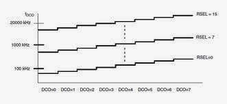
msp430 embedded c programming part2 - configuring DCO

Image
Introduction : MSP430 Clock system has three clocks which provides different frequencies . Need of three different clocks not only one is power consumption. That is we will use the clock with lowest frequency when we want to save the power and we will use the clock with highest frequency when we want high speed. The three clocks present in MSP430 are 1. MCLK(Master Clock) : Used by CPU and few peripherals such as ADC. It is  a high frequency clock but can be configured to provide a low frequency 2.SMCLK(Sub-Main CLock) : Distributed to Peripherals. It can be the same frequency as MCLK,or different depending on the application 3. ACLK(Auxiliary CLock) : Basically it is a low frequency clock, used for peripherals. There are four Sources for these clocks 1.LFXTCLK: As the name implies it is to use with low frequency crystal.A 32khz can be connected to msp430 for low power operation 2 XT2CLK:  This is not available in every device.it is to use with a second crysta...

msp430 embedded c programming part 1 --- Blinking a LED

/*   Blinking a LED which is connected to port 5.5 of the MSP430F2618 */ //step1 : include the microcontroller header file #include <msp430f2618.h> int main(void) { //step2 :  stop the watchdog timer,otherwise it will reboot the system if the timer fires WDTCTL=WDTPW+WDTHOLD; //WDTCTL is  a 2 byte register in which the least 8 bits are used for controlling the watchdog timer and 8 most significant bits are for setting the password for the watchdog timer as it is password protected.Setting the 7 lsb bit will stop the watchdog timer which is the value of WDTHOLD(0x0080) and the password for the Watchdog timer is 0x5a which WDTPW(0x5a00) has in it //step3: setting up the pins /* There are basically 5 registers for each port PxSEL -> Select the functionality PxDIR -> Selecting the direction of pin whether it is input(0) or output(1) PxIN  -> Input Register of the port PxOUT -> Output Register of the port PxRE...