TIVA Launchpad TM4C123 Part 1 - Blinking RGB LED
Before we start writing programs, we need to install the following softwares.
1. Download and install the latest version of Code Composer Studio (CCS):
http://processors.wiki.ti.com/index.php/Download_CCS
2. Download and install the full version of TivaWare from below link. The file name to download is SW-TM4C-x.x.exe
http://www.ti.com/tool/sw-tm4c
3. Download and install the latest LM Flash Programmer
http://www.ti.com/tool/lmflashprogrammer
4. Download the TM4C123GHGPM Microcontroller datasheet and User Guide
http://www.ti.com/lit/ds/symlink/tm4c123gh6pm.pdf
http://www.ti.com/lit/ug/spmu296/spmu296.pdf
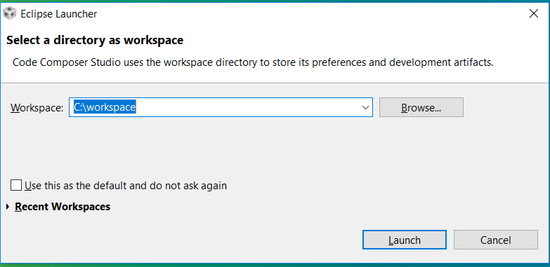
5. Run the Code Composer Studio


8. On the board, PF1 is connected to RED LED, PF2 is connected to BLUE LED and PF3 is connected to GREEN LED.
GPIO Registers in TM4C123:
Data Direction Register (GPIODIR): Set the input pin as output/input
Data Register (GPIODATA): Write to the pin or read from the pin
Pull Up Register (GPIOPUR): Pull up the pin
Digital Enable Register (GPIODEN): To select the digital I/O Functionality of the Pin
Clock Enable (RCGCGPIO): This register is common for all ports, and used to enable the clock source for the port. If Port is not used, we can disable the clock source to save power. Access to the port registers with clock not enabled will result in hard fault and the program crashes.
Steps to Blink LED
1. Enable the clock source of PortF
2. Set the direction of PortF PF1, PF2, PF3 as output using Data Direction Register
3. Enable the Digital I/O feature of PORTF PF1, PF2 and PF3
4. Write HIGH on the PORTF pins to set the LED
5. Call a delay
6. Write LOW on the PORTF pins to clear the LED
7. Call a delay
8. Repeat the steps 4 to 7
main.c:
To build the project, Right Click on the Project in the LED_BLINK and click on "Build Project"
To flash the firmware, we need to generate the .bin file. Code Composer generates .out file.
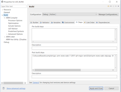
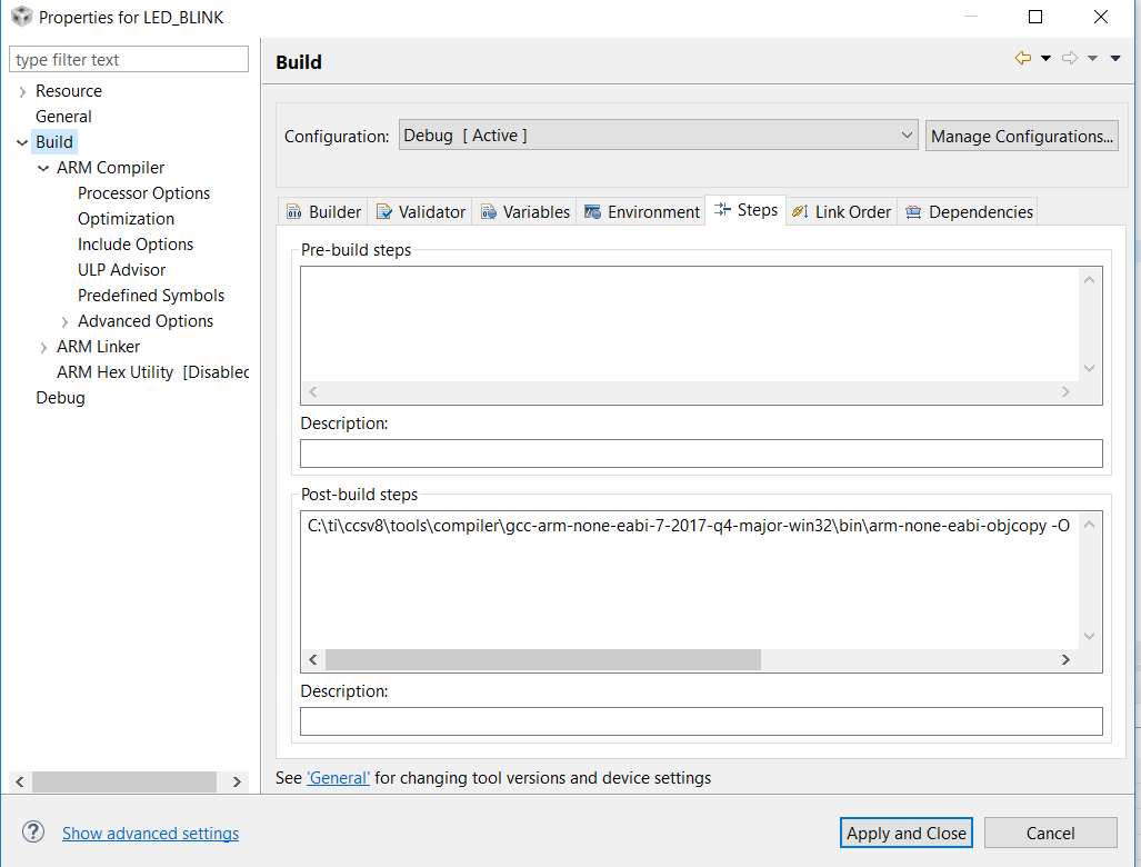
To generate a .bin file, right click on the project, click on Properties and Click On Build, then steps and add the following in Post-build steps.
C:\ti\ccsv8\tools\compiler\gcc-arm-none-eabi-7-2017-q4-major-win32\bin\arm-none-eabi-objcopy -O binary "${BuildArtifactFileName}" "${BuildArtifactFileBaseName}.bin"
Now, right click on the project in the project explorer and click on Rebuild Project.

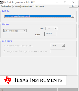
To flash the firmware on the TIVA board, connect the board to the PC over USB and open LM Flash Programmer and Select "TM4C123G Development Board"
Click on "Program" tab and browse the ".bin" file and Select the other options as per the screenshot

Click on "Program" to flash the firmware
1. Download and install the latest version of Code Composer Studio (CCS):
http://processors.wiki.ti.com/index.php/Download_CCS
2. Download and install the full version of TivaWare from below link. The file name to download is SW-TM4C-x.x.exe
http://www.ti.com/tool/sw-tm4c
3. Download and install the latest LM Flash Programmer
http://www.ti.com/tool/lmflashprogrammer
4. Download the TM4C123GHGPM Microcontroller datasheet and User Guide
http://www.ti.com/lit/ds/symlink/tm4c123gh6pm.pdf
http://www.ti.com/lit/ug/spmu296/spmu296.pdf
5. Run the Code Composer Studio
6. File -> New -> CCS Project
7. Select 'TIVA TM4C123GH6PM' from the drop down list, enter the Project Name: 'LED_BLINK' and click on 'Finish'

GPIO Registers in TM4C123:
Data Direction Register (GPIODIR): Set the input pin as output/input
Data Register (GPIODATA): Write to the pin or read from the pin
Pull Up Register (GPIOPUR): Pull up the pin
Digital Enable Register (GPIODEN): To select the digital I/O Functionality of the Pin
Clock Enable (RCGCGPIO): This register is common for all ports, and used to enable the clock source for the port. If Port is not used, we can disable the clock source to save power. Access to the port registers with clock not enabled will result in hard fault and the program crashes.
Steps to Blink LED
1. Enable the clock source of PortF
2. Set the direction of PortF PF1, PF2, PF3 as output using Data Direction Register
3. Enable the Digital I/O feature of PORTF PF1, PF2 and PF3
4. Write HIGH on the PORTF pins to set the LED
5. Call a delay
6. Write LOW on the PORTF pins to clear the LED
7. Call a delay
8. Repeat the steps 4 to 7
main.c:
To build the project, Right Click on the Project in the LED_BLINK and click on "Build Project"
To flash the firmware, we need to generate the .bin file. Code Composer generates .out file.
To generate a .bin file, right click on the project, click on Properties and Click On Build, then steps and add the following in Post-build steps.
C:\ti\ccsv8\tools\compiler\gcc-arm-none-eabi-7-2017-q4-major-win32\bin\arm-none-eabi-objcopy -O binary "${BuildArtifactFileName}" "${BuildArtifactFileBaseName}.bin"
Now, right click on the project in the project explorer and click on Rebuild Project.

To flash the firmware on the TIVA board, connect the board to the PC over USB and open LM Flash Programmer and Select "TM4C123G Development Board"
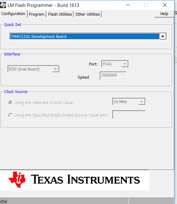
Click on "Program" tab and browse the ".bin" file and Select the other options as per the screenshot

Click on "Program" to flash the firmware

I would really like to appreciate your work. This is damn good. It really helped me out.
ReplyDelete