TIVA Launchpad TM4C123 Part 2 - Push Button
SW1 Push button is connected to PF0 Pin, SW2 Push button is connected to PF4 Pin. Notice that there is no pull up resistor connected to SW1 or SW2. To use SW1 and SW2 we need to enable the internal pull-up resistor for PF0 and PF4 pins.
Steps for Switching Green LED on SW1 push and RED Led on SW2 Push
1. Enable the clock to PORTF
2. Set the Direction Register PF4, PF0 as input and PF1, PF3 as output
3. Select the Digital I/O feature of PORTF
4. Enable the pull-up resistor option in PUR register for PF0 and PF4 pins
5. Read GPIODATA value and set the LED depending on which button is pressed
6. Repeat Step 5
For SW2, extra steps need to be taken as PF0 pin to which SW2 is shared with NMI. To prevental accidental write to configuration registers and thus NMI, the configuration register bits for PF0 are normally locked. It may be unlocked by writing a passcode value of 0x4C4F434B to the LOCK register followed by setting bit 0 of the commit register.
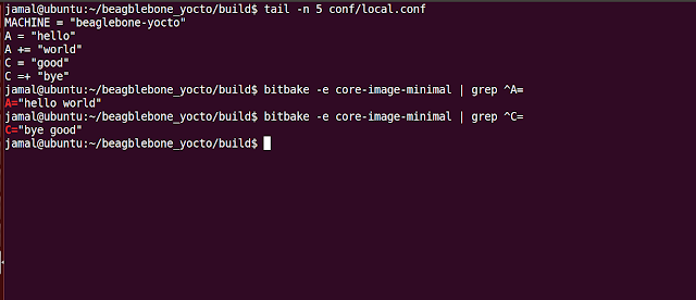
main.c
Now press SW1 and you can GREEN led will ON and pressing SW2 will make RED led ON
Steps for Switching Green LED on SW1 push and RED Led on SW2 Push
1. Enable the clock to PORTF
2. Set the Direction Register PF4, PF0 as input and PF1, PF3 as output
3. Select the Digital I/O feature of PORTF
4. Enable the pull-up resistor option in PUR register for PF0 and PF4 pins
5. Read GPIODATA value and set the LED depending on which button is pressed
6. Repeat Step 5
For SW2, extra steps need to be taken as PF0 pin to which SW2 is shared with NMI. To prevental accidental write to configuration registers and thus NMI, the configuration register bits for PF0 are normally locked. It may be unlocked by writing a passcode value of 0x4C4F434B to the LOCK register followed by setting bit 0 of the commit register.
main.c
Now press SW1 and you can GREEN led will ON and pressing SW2 will make RED led ON

Hi sur I deal with a problem in tiva c could you please help me about this subject?
ReplyDelete